LS2-4A-AQL Installation Guide

LS2-4A-AQL Installation Guide

Getting Started

Unpacking

Carefully remove all items from the shipping box and inspect.  Make sure there are no broken parts or anything missing (see next page for box contents).  If you received multiple units, they may be labels that identify each unit according to information shared during the sales process.

Working Area

Make sure the area where the control panel is being installed is safe and clear of debris and hazards.  Make sure the doorway is also a safe working environment.  You may need to warn patrons that the door will be blocked from time to time during installation.

Read Ahead

Please read this guide in its entirety prior to starting.  Hardware warranty is void if instructions are not followed and hardware is damaged. 
When in doubt, please call our Help Desk at 866-739-8588 option 2.

Box Contents

Control Panel


Piece Parts

Controller Overview

Connection Diagram


Pre-wiring

Units are delivered pre-wired, connecting power, relay, and triggered outputs.  Do not remove any of the existing wirings unless instructed by Latitude Security.  


Installation Preparation

Tools


Cable


Pre-Install Checklist

  1. Working Internet connection (Ethernet or Wi-Fi)
  2. All required permits have been applied for and approved by the proper authority
  3. Install site has no hazardous working conditions
  4. Electric lock(s) are operational and use 12-24VDC power
  5.  THESE INSTRUCTIONS HAVE BEEN READ IN ENTIRETY PRIOR TO ATTEMPTING TO INSTALL

Physical Inspection

  1. Identify the location where the LS-2 enclosure will be mounted. 
    1. Near a standard 110 VAC outlet
    2. It should be central to where cabling can be easily routed to/from. 
    3. Although the enclosure is tamper-proof, it is good practice to place it in a secure area to avoid tampering and/or being out of reach.
    4. Avoid high humidity
    5. Avoid extreme heat or extreme cold
  2. Identify the location of the card reader or PIN pad.
    1. Mount within 6” of the same height as the door handle
    2. Mount near the door
    3. Mount on the UNSECURE side of the door (outside)
  3. Identify cable routing
    1. Any visible cable should be 8’ or higher
    2. Cable below 8’ should be in conduit, wire mold, or inside a wall
    3. When factoring distance includes vertical (height) distance in addition to the span between enclosure and devices.

Cabling

This section provides instructions for wiring the card reader and the two most common types of locks, electric strike, and magnetic lock. 

Reader Cabling

A dedicated cable should be run from the control panel to the reader.  It is recommended that 22 gauge, 6 conductors, shielded cable (AWG 22/6, shielded) be used. 

Reader Mounting

Latitude supplies readers in two different sizes:  Narrow, which is designed to mount on a door frame, also known as a mullion.  The other is a standard one-gang mount.  These readers are designed to fit on a standard single outlet box. 

Readers should be mounted between 34 inches and 48 inches from the ground.  This ADA code for door handles and readers must follow suit since they are a form of ingress.  


For detailed mounting instructions, please refer to the documentation provided by the reader manufacturer.

Reader Connection

Use the wire colors according to the diagrams provided by the reader type.  It is recommended that DOLPHIN (blue) connectors or WAGO connectors are used to join wires between the reader pigtail and cable going to the control panel.  Please avoid using wire nuts.  Dolphin connectors are good for fitting into tight spaces, however, they are permanent connections and the wire must be cut to redo a connection.  Wago connectors are preferred because they work with a wide range of wire gauges, and they don’t require wires to be cut to redo a connection, although they may not fit in some smaller areas.


Using Dolphin Connectors


Using Wago Connectors


Typical Card Reader Pigtail Wire
Farpointe P500, P300, P620, P640

G900 Optical Barcode Reader

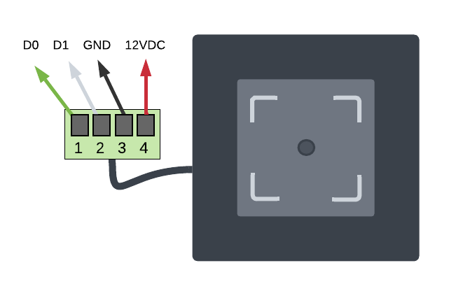
M350 Optical Barcode Reader


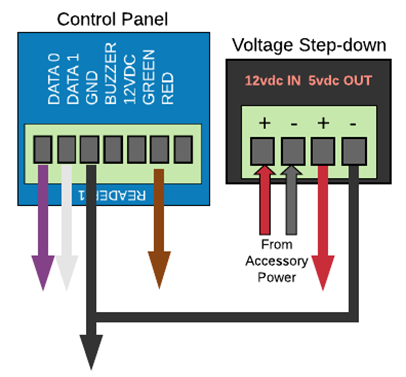
Control Panel Connections by Reader Type

Proximity Readers
    
Barcode Readers

IMPORTANT: Requires 5VDC power.  Must use voltage step-down (~12v to ~5v) to power reader.


Lock Cabling

Locks and exit devices should have a dedicated cable, therefore, not to create any unnecessary electrical interference with the reader, since the reader is a communication device.   

There are multiple methods for wiring locks, however, the methods described in this guide are what is recommended by Latitude for a non-retrofit situation.  A retrofit situation consists of cases where this system may be running in parallel with another system or connecting to existing locks and power. 

Electric Strikes & Rim Devices

Strikes and rim devices operate in the same way in that power is sent to the lock to release (open) the lock.  These electric locks should be installed on doors where exiting the room doesn’t require the lock to be operational, therefore, making for a safer environment in the event of an emergency.  

IMPORTANT:  LOCKS MUST BE 12 VOLT DC ONLY

Door & Cabling Examples

Electric Strike with Lockset (mortise or cylindrical)


Electrified Exit Device


Magnetic Locks

Maglocks are simple by design but require more circuitry to maintain a safe environment.  Maglocks are always “ON” when the door is locked.  This means power is being sent to the device in its normal state.  Power to the door must be interrupted to release the door.  The ability to intuitively interrupt power, therefore releasing the lock, under any circumstance when exiting the building is required. 
The following cabling diagrams cover two scenarios:  The first is a typical installation using a push bar exit device, which is one of the safest methods when implementing maglocks.  The second scenario incorporates connections for a motion sensor and a push-button exit.  When using a motion sensor to release the maglock, a secondary (redundant) exit device is required, such as a button release. 18-24 gauge wire is recommended for wiring locks.  When wiring a push bar exit, an 18 gauge, 2-conductor would be the most effective and easiest to manage.  When wiring a motion device, exit button, and lock, a 6-conductor cable is best.  

Maglock with Push Bar Exit Device

Maglock with Motion Sensor (REX) and Push Button Exit


Testing

This section provides instructions for wiring the card reader and the two most common types of locks, electric strike, and magnetic lock. 
A test card is provided in the plastic bag containing the piece parts.  This card has been pre-programmed with the system, therefore, door functionality can be tested without the control panel being connected to the Internet.
  1. Power the system and wait about 3 minutes for the system to fully boot prior to performing any tests.
  2. With the test card in hand, go to the reader and scan the card. 
    1. Did the light on the reader turn GREEN for 5 seconds?
    2. Did the door unlock and stay unlocked for 5 seconds?
  3. Test exit devices (typically with maglocks):
    1. Does the motion sensor unlock the door for 5 seconds?
    2. Does the button unlock the door?  Depends on the setting, but unlock period should be between 10-30 seconds.
  4. Contact Latitude Customer Support to complete testing or troubleshoot any issues:  +1(866)739-8588 Option: 2

Panel Status


Wi-Fi Configuration

Get Ready:
  1. Computer (PC, laptop, or Mac) with Ethernet (RJ-45) cable connection
  2. Ethernet patch cord
  3. The access control system must be powered on.
Perform Steps:
  1. Deactivate Internet connection on computer (disconnect wi-fi, for example).
  2. Using patch cord, connect the computer to port labeled ADMIN on the controller.
  3. Open an Internet browser and enter the following IP address in the address bar: 192.168.207.1
  4. When prompted, enter the following:
  5. Username: cli
  6. Password: new5cli
  7. Navigate to Networking Admin Interface >> Networking >> WiFi.

  1. Make sure the Enable WiFi checkbox is checked.
  2. Enter the SSID name of the network you want to connect to.
  3. Enter the WPA Passphrase (password).
  4. Click Save.
  5. Navigate to Networking >> Troubleshooting
  6. Review the results of the Wifi Tests.  If the test fails, review the previous steps to ensure the settings are correct. 

  1. Disconnect computer from the control panel

Warranty & Support

Warranty

All hardware provided by Latitude Security carries a two-year (2) limited warranty from the commission date (printed on the front of the control panel).  All installation services provided by Latitude Security, or its subcontractors have a one-year (1) warranty from the install date. 

Customer Support Requests

  1. Customer Portal: https://support.latitudesecurity.com/
  2. Phone: +1 (866) 739-8588 option 2
  3. Email: support@latitudesecurity.com

Billing Inquiries

  1. Email: billing@latitudesecurity.com
  2. Phone: +1 (866) 739-8588 option 3

    • Related Articles

    • LS2-3A-ALX Installation Guide

      Getting Started Unpacking Carefully remove all items from the shipping box and inspect. Make sure there are no broken parts or anything missing (see next page for box contents). If you received multiple units, they may be labels that identify each ...
    • Camio Hardware Installation Guide

      Camera Angle Whether a camera was purchased specifically for your tailgating solution or you are using cameras from an existing system, certain guidelines regarding the camera angle must be met in order to have accurate results. Please install or ...
    • Barcode Reader Installation - M350 Optical

      Overivew The following guide provides details for mounting and wiring the M350 Optical barcode reader. Wiring The reader has pigtail with a phoenix connector. The connector has four (4) inputs, Data1, Data0, Ground, 12VDC, which supports the Wiegand ...
    • Amazon KfB Installation

    • Brivo Access Cam Installation